Railing Scenarios & Sketches

Below are a series of typical guardrail attachment methods, which highlight some problems with current practice. Where does your railing fit?
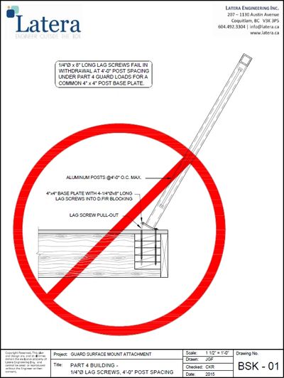
- The lateral loads on guards cause very high tensile forces at the baseplate. ¼” diameter lagscrews do not have sufficient withdrawal resistance for these loads even at 8” long. (See BSK-01)
- For bolted connections, the compression of the wood must be considered. A typical 4”x 4” post base plate does not have sufficient bearing area to spread the load, and wood crushing results. (See BSK-02)
- The proprietary and patented “Breyce” addresses both the withdrawal concerns and the wood crushing by transferring the load directly to the wood joists. (See BSK-03)
- Where the guardrail is secured directly to the fascia, it is important that the fascia have sufficient attachment to the structure to prevent tearing under the guard load. (See BSK-04)
- Where additional attachment of the fascia to the structure is provided, the attachment of the guard to the fascia must still be considered. 6 – ¼” diameter x 4 ½” long lag screws are not sufficient to resist the lateral loads on the guardrail. (See BSK-05)
- 6 – 3/8” diameter x 4 ½” long lag screws are sufficient to resist the lateral loads on the guardrail provided the blocking is Douglas fir. If a less dense species is used for blocking, this detail would fail. (See BSK-06)
- The proprietary and patented “Breyce” transfers the load directly to the wood joists enabling greater post spacing that would be possible with a typical lag screw connection. (See BSK-07)
Some conditions involve short continuous top rails where the load on the base connection is considerably reduced. We recommend considering the above sketches as valid where the guard length is greater than 12'0", or the top rail is not continuous across multiple posts.
This website uses cookies.
We use cookies to analyze website traffic and optimize your website experience. By accepting our use of cookies, your data will be aggregated with all other user data.